OK, so in point of fact this build began back in May of 2009, but it’s taken me a fair while to get around to setting up the blog and doing much about it, and I’ve had large gaps, so I’m still firmly in the build phase 4 months later. Bear with me, there will be a fairly long series of posts while I catch up…
So, having assembled my raw materials as described in previous installments, I now had a room full of MDF, electronic bits and pieces, and computers. Which I needed to turn into a working sim. Where to start?
Fairly obviously, with the shell. Recall that for this phase of the project I’m only building the console and pedestal, not an enclosure, so this made things a bit simpler. I first attempted to build some 3D models in Google Sketch-up, but this proved to be a frustrating enterprise. I ended up with something promising, but turning it into a set of blueprints would be hard. As I’ve mentioned previously, I’m a hands-on, wade in kind of guy, and so based on my experience in previous DIY projects I set to work with a basic idea in my head but not much more.
Dimensions were worked out from various online sources. Remember that I’m not attempting to replicate a particular model of aircraft, so precise measurements for one type or the other weren’t needed. I just worked out what the average dimensions seemed to be across a variety of different projects. One limitation from the start was that the MDF sheeting I had was 1.2m long – I was unable to transport or work with longer pieces because of space constraints. So the widest my console was going to be was 1.2m plus 18mm thickness of MDF at either end. This is a little narrower than most airliner consoles, but OK for a light jet.
Here’s a series of (slightly blurry) photos of the basic assembly of the console shell. More details after the jump.

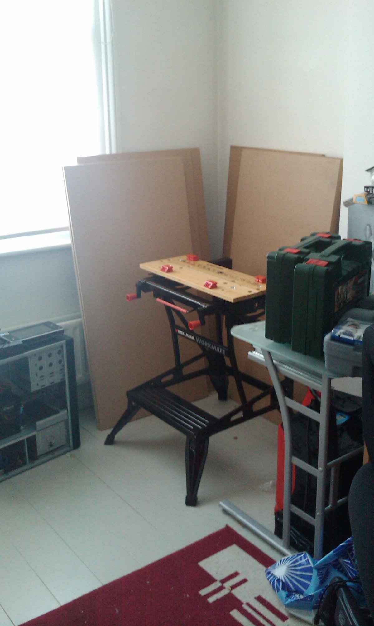
Tools and materials stand ready

The first cuts are made

Sides meet span

Dowels and angle brackets are used to secure the joins, Ikea-style

Top panel goes on in the same manner, and the basic structure is done

Bracing structures are added to support the weight of the LCD screen
Getting to this point took a few days, though a sufficiently committed builder could probably do it in a day. It was hot, I was lazy, what can I say? Already you can start to see the plan emerging – a simple console with an angled front panel, space underneath where the pedestal will eventually connect and pilot and co-pilot feet will hit rudder pedals (which for phase 1 are simply plain CH Products pedal sets, but in phase 2 will probably be rebuilt to be closer to the real thing).
Most people seem to keep their FS computers separate, but I’m going to go integrated – the motherboards, PSUs and disks will sit inside this structure along with the requisite USB hubs, networking gear etc. You’ll simply plug the console into the mains and network and go.
This is intended to be a two-seat cockpit. At the beginning I considered doing a single-sided build; this is not uncommon especially with the pre-fab 737 cockpits where it’s cheaper to buy just the pilot’s side and console. In the end, despite the fact that 99% of the time it’ll just be me using it, I decided to go with a more traditional layout.
This was the last point in the build at which things were relatively straightforward. Thereafter I entered a world of do and re-do, especially with the glareshield and front panels which have gone through several iterations.
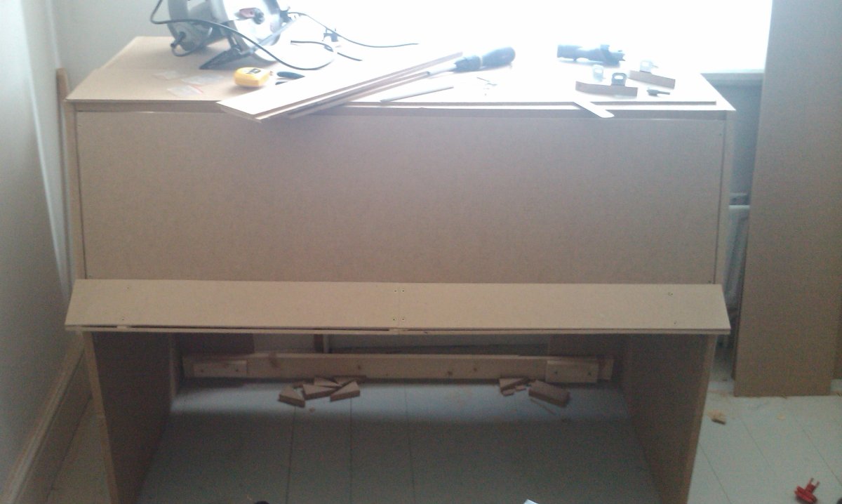
Some tips I can share from this part of the build: your console is going to need to be firm and well-braced, even if it’s not supporting a large load on top like mine will be (the 46″ LCD TV I’m using for the phase 1 display). Wobbling is not good. MDF is stiff but your joints will not be, even with the use of dowels. If you’re a master woodworker you might like to consider making proper mortice joints, but then you’d probably be better off working with wood and would lose the advantages of MDF. Even with lots and lots of long screws driven into all the joined edges, and numerous support brackets, the console still wobbled. In the end I realised that the open bottom was the problem. As a short-term solution I screwed a full-width baton to the bottom of the console at the rear – this braces the sides at the bottom as they are at top and middle, and has made the whole structure very stiff and unyielding.
As previously advised, be very careful when drilling or screwing into the edges of MDF boards. Even the thicker boards (I’m using 18mm as my maximum strength material) will tend to split if you don’t get it right. Using a clamp to clamp down on the area being screwed into can help, but the best technique I found was to drill a hole with a wood bit 1mm narrower than the screw, to about the depth the screw will go. This removes enough material that when the screw goes in, it tends to do so without splitting the board.
If you’re not building the thing so it can be taken apart (which I have had to due to my upcoming house move) then a good grab adhesive is your friend here. It’ll work wonders in conjunction with a few screws. I’ve avoided nails in this build altogether, but for a permanent construction you could consider using them for wood joins. A nailgun will make this all the easier.
Once this structure was built, I had a go at building a front panel. I also decided to add a projecting sloped panel, rather like the 737 or the D-Jet which was my inspiration. This proved to be a most frustrating part of the build, long-term, but initially I simply cut some triangular supports and 6mm MDF boards to serve as panels (this was before I decided to go with backlit panels). Sadly the results were not what I’d hoped and it rapidly became obvious that a single-panel front would not cut it (and would look awful too). Some pics of the blind alley follow…

A support piece being prepared for chiselling

I ended up with four of these

Put it together with some 6mm MDF panelling and... FAIL
The MDF supports turned out to be useless since I had to drill into the edges a lot and they kept splitting. In the end I re-did the supports using softwood (no photos of that, sorry!) and redid the panels as try to get the edges as straight as I could. Actually, making a straight saw cut is a subject for another post, but it’s harder than it looks without a table saw.
At this point I moved on to the glareshield, which is a long and sorry story, and a subject for a future post.
